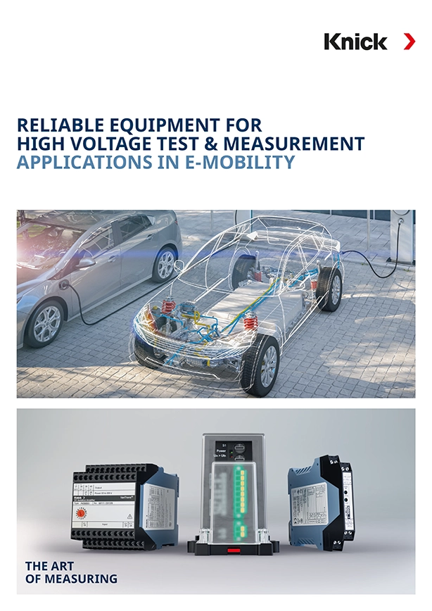
Battery cycler – testing high-voltage batteries
The test device especially developed for this purpose, a “battery cycler,” analyzes the function of the battery. The power of the battery during the charging and discharging cycles is measured over a specific period of time.
Key facts about the application
Sector
Energy storage/electric vehicles
Application
Analysis of the charging and discharging operations or before delivery, checking that the charging status of an electric vehicle is correct
Measured parameters
Voltages up to 2000 V DC (and higher)
Main requirements
Selectable DC measurement configurations (up to 2000 V DC)
Direct current measurement (via shunt voltage)
Precise conversion into standard control signals
Safety with 100 % isolation of dangerous voltages between the battery and test device
Configurable frequency response (10 Hz to 10 kHz)
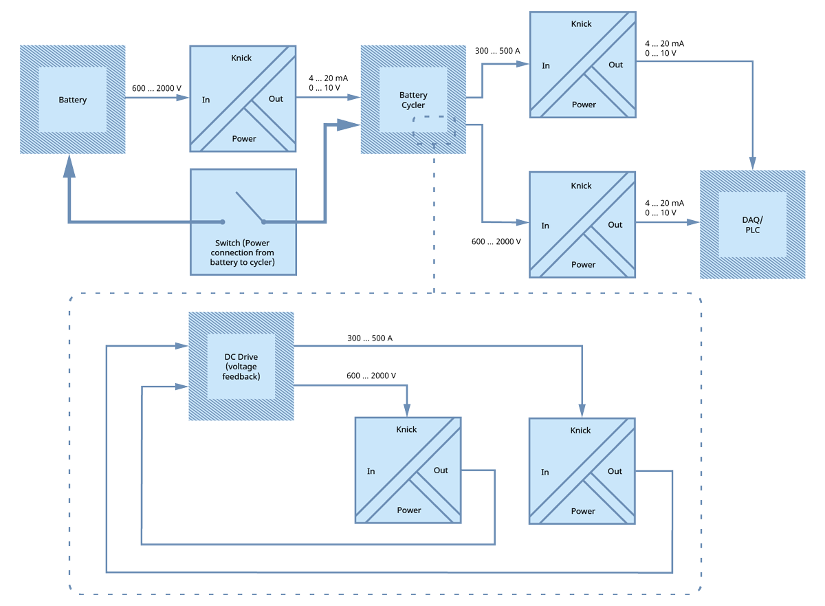
Safe and efficient measurement of high-performance batteries
Description of application
During battery tests, the charging and discharging operations (battery cycles) are continuously simulated in a HIL (hardware in the loop) configuration that corresponds to the typical use profiles when the electric vehicle is in operation. A series of parameters is measured, including capacity, battery efficiency, and self-discharging.
The diagram shows that there are three main areas for Knick products:
- “Compensating voltage” – is used to ensure that the battery voltage is the same as the voltage visible in the cycler. As soon as the voltage is compensated, the switch between the battery and cycler is closed so that the charging/discharging operations can be carried out.
- Transfer of voltage and current of the battery cycler to DAQ (data tracking) or the PLC. This increases transparency for end users.
- The battery cycler is equipped with a direct current drive. It is mapped in the circuit diagram by a breakout box. Here, transducers help with the key applications of “voltage and current reversal.” These products return control signals that represent the voltage and current actually supplied to the direct current drive unit.
With them, it is possible to ensure that the power expected from the drive is equal to the actual power and a short circuit is not present.
Requirements of the application
Precise and fast direct voltage and current measurements at battery cyclers are indispensable for effective function. The safety of operating personnel and the measuring device must always be ensured, since the voltages applied in these applications are increasingly higher. Currently, they are as high as 2000 V DC.
If, in addition, the installation space in the enclosure is limited – which is often the case for test devices in production – and if many battery cells are to be tested at the same time, the design of the high-voltage transducer becomes very important. Small size and easy mounting on DIN rails are the crucial factors here.
Why Knick?
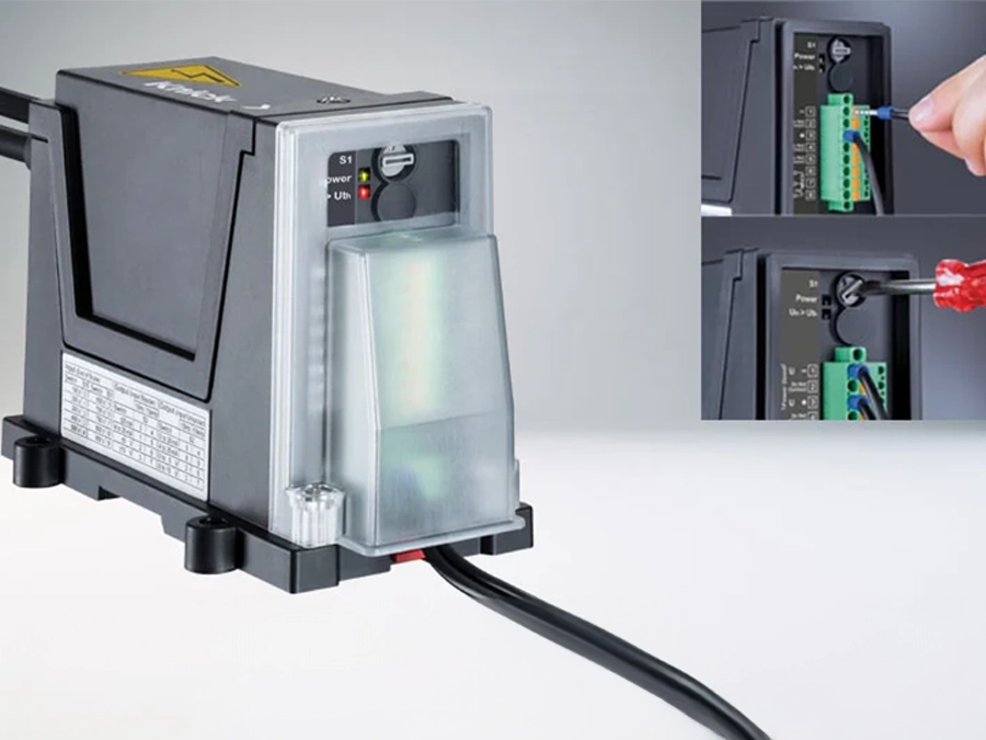
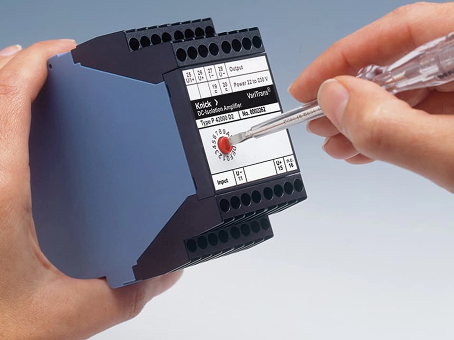
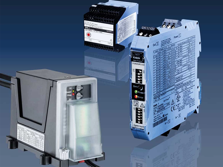
The Knick P42000 high-voltage transducer was developed for measurements on the circuitry of power electronics and safely converts voltages of up to 2000 V DC into standard output signals of ±20 mA, ±10 V or 4 … 20 mA. The performance characteristics of the device have been proven in many other high-voltage applications from the power generation sector, which is why the device is ideal for complex energy storage and electromobility applications.
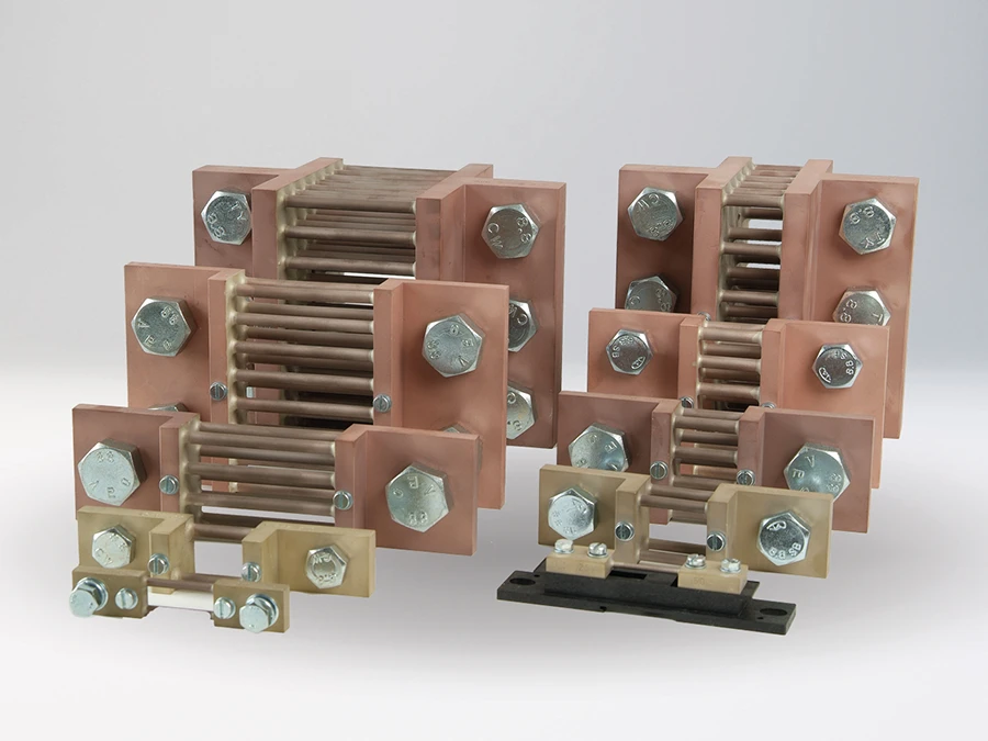
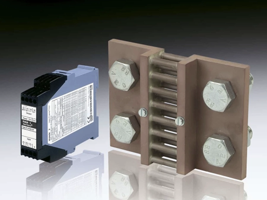
The Knick P41000 high-voltage transducer measures direct currents of up to 20 kA in conjunction with a shunt. It features continuous isolation of up to 3.6 kV. Shunt voltages (e.g., +/- 50 mV, 60 mV, 100 mV) are converted into standard output signals of +/- 20 mA, +/- 10 V or 4 … 20 mA. Due to its high power specification, it is ideal for critical energy storage and electromobility applications.
Matching Products
Associated industries and applications
Overview of measuring technology applications and product solutions for electromobility


