Power hardware in the loop
An example: With an HIL test, prototypes like traction inverters can be tested in different battery, charging, and error situations without having to carry out trials on dynamometer test benches or directly in a vehicle. With HIL systems, products can be developed more quickly and less expensively, since all relevant drive components are simulated and test objects can be tested variably under real conditions.
Key facts about the application
Sector
HIL simulation for tests in product development and prototyping
Application
Emulation of the conditions inside a vehicle and the effects on the high-voltage components
Measured parameters
0-10 V and 0-20 mA standard signals for control functions
Main requirements
The isolation of the test equipment must be designed for the high nominal and maximum system voltages
Since a fast dynamic controller is often necessary, signal transmission must also be fast, i.e., as immediate as possible
To receive reliable test results, a high level of precision is necessary
A test with emulation of high-voltage components also requires high output isolation – in contrast to commercial products.
Test for high-voltage systems
Description of application
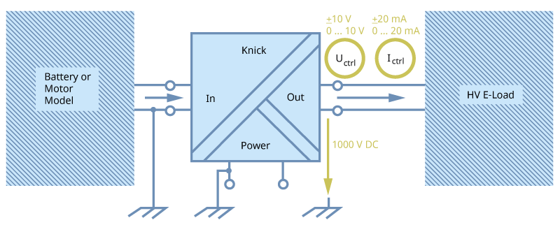
When signal conditioners are applied in high-voltage environments, it is generally normal to plan the highest isolation on the input side. In this case, the output is often connected to a controller with low, grounded voltages. With the increasing number of hardware-in-the-loop tests in the electromobility sector, today the voltage sources is often at the output side of the configuration. The test systems generate signals in order to simulate the conditions prevalent in the vehicle system and in turn, the effects on the high-voltage components.
Requirements of the application
The design and performance of HIL systems depend to a great extent on the devices that must be designed for the requirements for signal transmission and, at the same time, decouple all channels through electrical isolation. Simulating components in highly dynamic systems requires correspondingly fast and precise signal transmission.
Why Knick?
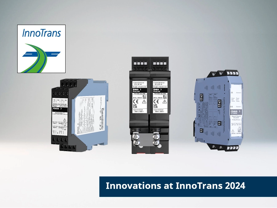
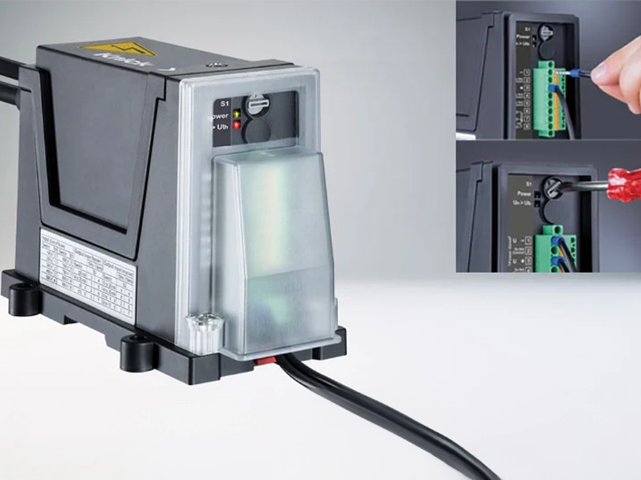
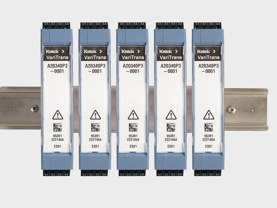
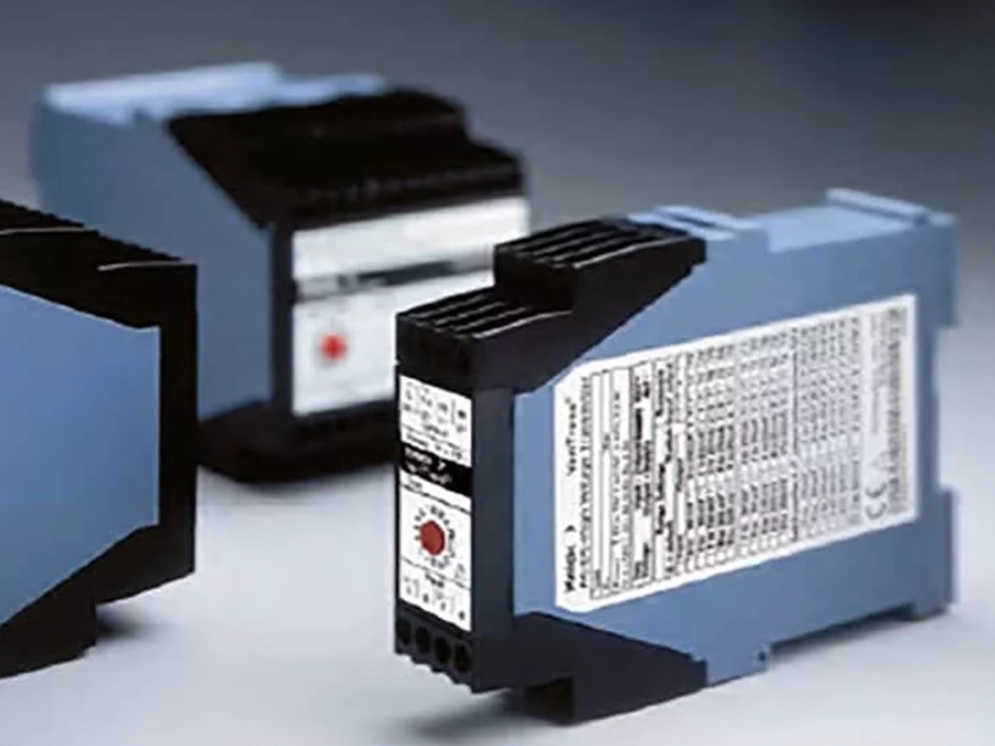
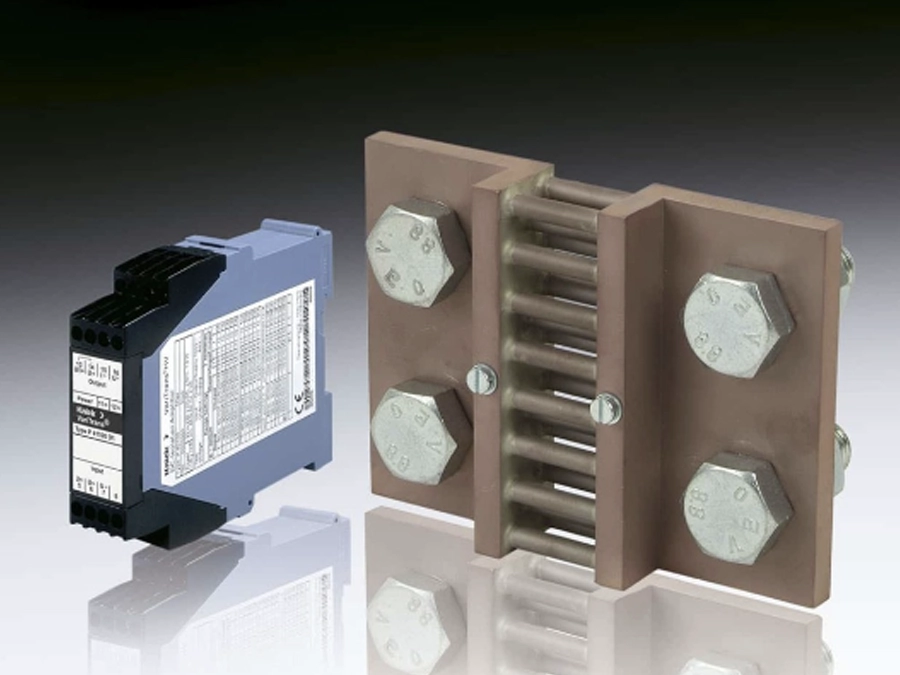
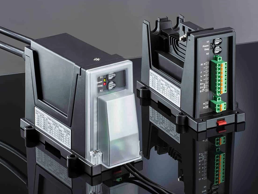
The P15000 and A26000 models from Knick (for bipolar measurements) can reliably transmit signals from a grounded emulated environment to components on high electrical potential.
The key feature of this solution is the high output isolation of 1000 V or more. Reduced dimensions and the ability to stack enable space-saving systems. The device has a response time T90 of 70 μs, a cutoff frequency of 10 kHz and an input-to-output transmission accuracy of with a gain error of < 0.1 % of the measured value.
Matching products
Associated industries and applications
Lorem Ipsum dolor sit amet
Lorem ipsum dolor sit amet, consetetur sadipscing elitr, sed diam nonumy eirmod tempor invidunt ut labore et dolore magna aliquyam erat, sed diam voluptua. At vero eos et accusam et justo duo dolores et ea rebum. Stet clita kasd gubergren, no sea takimata sanctus est Lorem ipsum dolor sit amet. Lorem ipsum dolor sit amet, consetetur sadipscing elitr, sed diam nonumy eirmod tempor invidunt ut labore et dolore magna aliquyam erat, sed diam voluptua. At vero eos et accusam et justo duo dolores et ea rebum. Stet clita kasd gubergren, no sea takimata sanctus est Lorem ipsum dolor sit amet.
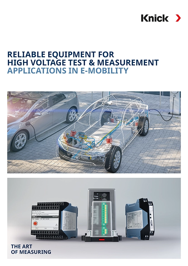
Overview of test and measurement specific applications and product solutions in e-mobility


