Testing battery management systems via simulated temperature changes
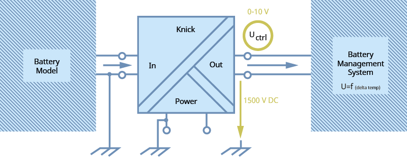
The test system generates control voltages in a battery model in order to simulate temperature conditions for battery management systems (BMS) and evaluate the temperature management of the BMS.
Key facts about the application
Sektor
Testing high-voltage components in electromobility
Application
Simulation of temperature changes to test a battery management system (BMS)
Measured parameters
0-10 V standard signal for control function
Main requirements
High quality of the signal conversion of simulated temperatures to evaluate BMS performance.
Safety through galvanic isolation of the voltages between the battery model and the BMS, to which higher voltage has been applied.
Simulation for testing a BMS
Description of application
The service life of batteries in electric vehicles depends in great part on the quality of the battery management system (BMS).
In each individual battery cell, parameters like charging and discharging current, voltage, and temperature are monitored.
It is particularly important to determine how the BMS reacts to temperature changes in the individual cells.
Evaluating BMS performance by exposing a battery cell to the entire temperature range in a climatic chamber is expensive and takes time. This is why temperature changes are often simulated. To do this, test systems generate control voltages in a battery model to test the temperature management of the BMS. Battery emulation used the battery voltage for which the BMS is designed. Currently, that is up to 950 V DC and in the future, will be up to 1500 V DC for commercial vehicles in particular and higher if necessary.
Requirements of the application
Accuracy and safety are required for suitable simulation of the temperature conditions under which battery management systems must operate.
Furthermore, the flexible choice of input and output signals is advantageous, since modified test scenarios could make adjustments to the signal ranges or signal types necessary. Higher flexibility also enables a single solution to be adapted to a range of possible signal conversion and conditioning requirements within the test environment.
Why Knick?
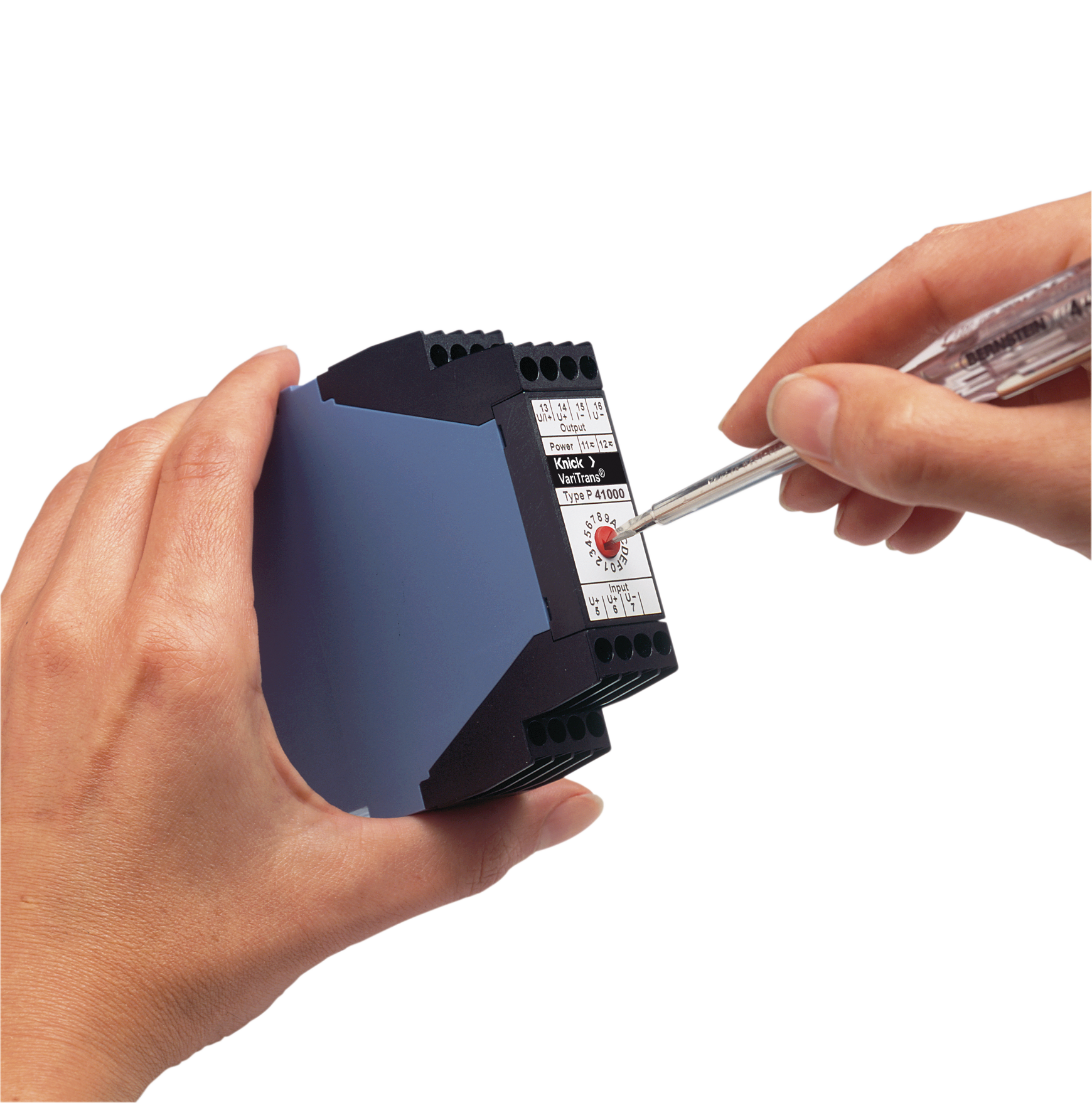
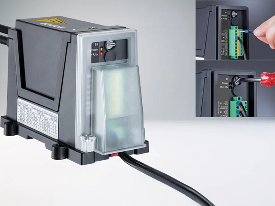
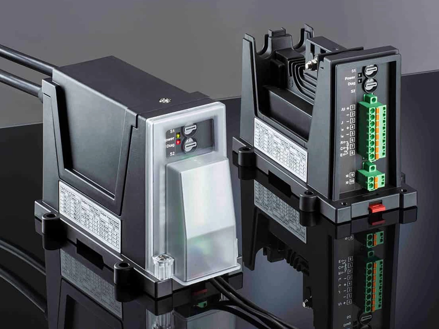
The P41000 high voltage transducer can transmit standard control signals from an input to an output. Here, the output is electrically isolated up to 1650 V DC against input and auxiliary power. The response time T90 is 110 μs and the cutoff frequency is 5 kHz. Flexibility is achieved via the calibrated switching of up to 16 freely selectable input and output ranges.
Matching products
Associated industries and applications
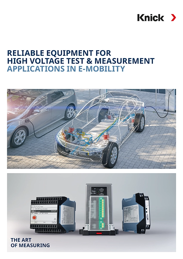
Overview of test and measurement specific applications and product solutions in e-mobility


