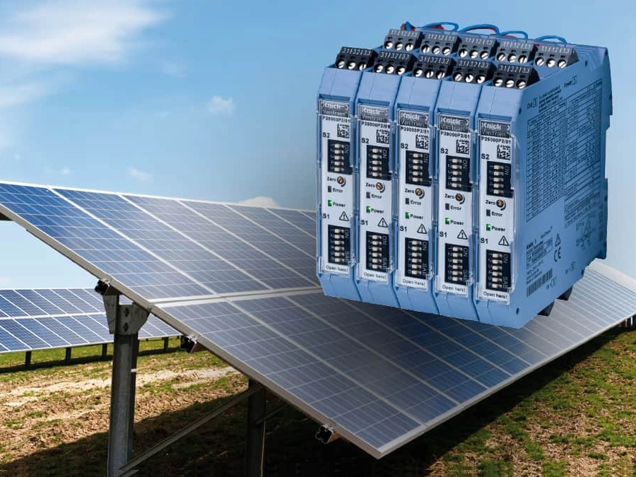
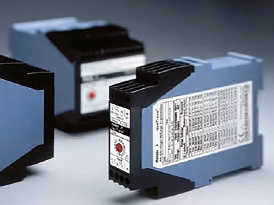
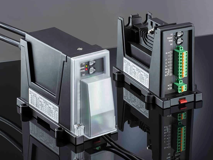
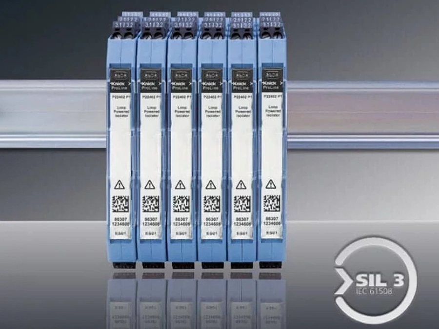
P41000 High Voltage Transducer / Transmitter | Calibrated and Switchable
Description
Universal high voltage transducers. Input signals from Vin = ±60 mV up to Vin = ±100 V.
- Universal high voltage transducers
for converting voltages, e.g. in shunt applications, from ±60 mV up to ±100 V to impressed ±20 mA, ±10 V or 4 ... 20 mA output signals. - New TransShield technology
enables extremely compact modular housings - Working voltages up to 3600 V AC/DC
- Protection against electric shock
with protective separation up to 1800 V AC/DC according to EN 61140 - Test voltages up to 15 kV AC
- Excellent transmission properties:
- Gain error < 0.1 %
- Cutoff frequency 5 kHz (low-pass filter / lower cutoff frequency on request)
- Rise time T90 approx. 110 µs
- Virtually no influence from common-mode voltages
CMRR >150 dB - High immunity to transient interference
T-CMRR >115 dB - Tremendous flexibility provided by
- Calibrated switching of up to 16 input/output ranges (working voltage up to 2200 V)
- Up to 16 customer-specific measuring ranges
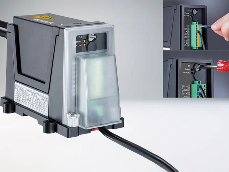
- 20 V to 253 V AC/DC broad-range power supply
- Reliable function even with unstable supply
- No damage in the case of erroneous power connection
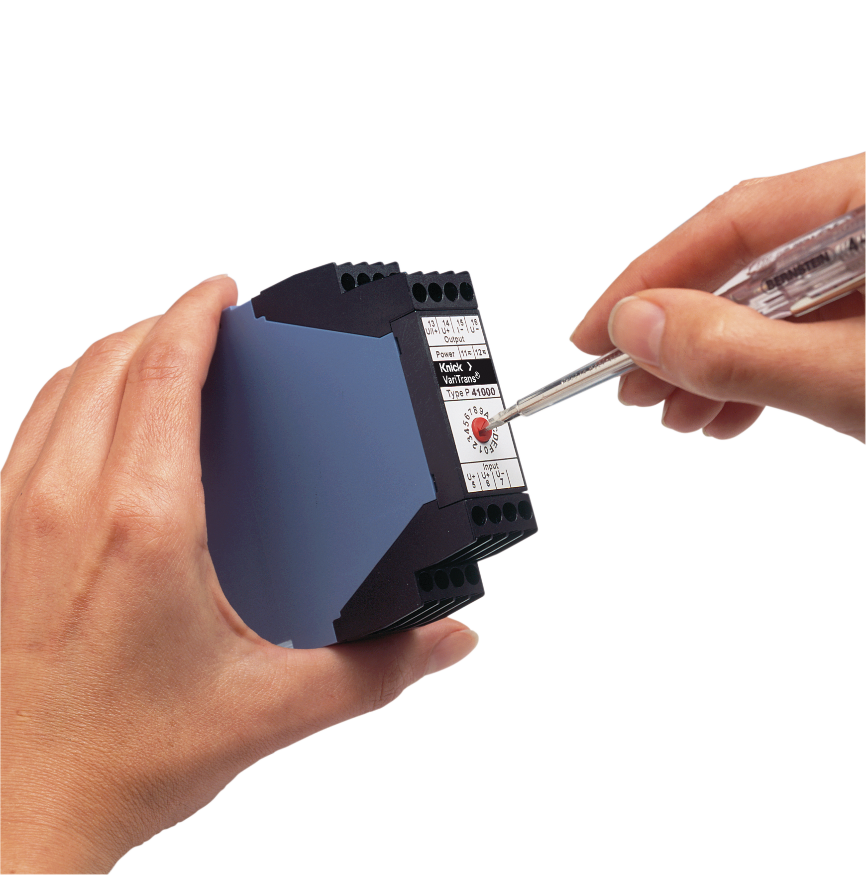
- Switchable models
minimize required device variants and save stockkeeping costs - Robust
thanks to vacuum encapsulation - Suitable for DC railway systems
up to 3000 V DC - Mechanically stable
for operation on ships, rail vehicles and land crafts - 5-year warranty
The P41000 isolation amplifiers have been specially conceived for measurements of bipolar voltages from millivolts to volts. They reliably isolate high potentials at the input circuit. The isolating distances are designed to withstand permanent voltages up to 3600 V AC/DC and fast transients up to 20 kV.
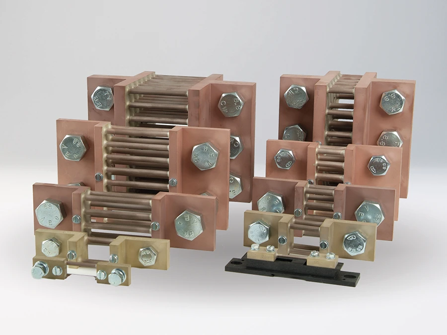
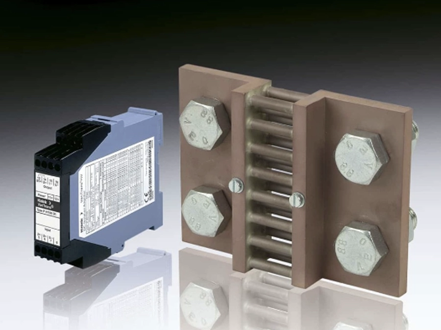
Protection against electric shock is achieved through protective separation according to EN 61140 between input and output and power supply. Specially designed for current measurements using a shunt resistor.
We look forward to hearing from you!
Contact Us
| Function: | Current measurement via shunt resistor on high potential |
|---|---|
| Input: | 0 ... (±)50 mV up to 0 ... (±)100 V |
| Output: | 0 ... (±)10 V, 0 ... (±)20 mA, 4 ... 20 mA, peak or TRMS values |
| Isolation AC/DC: | up to 3,600 V |
| Test Voltage: | 10/15 kV AC |
| Power Supply: | 22 ... 230 V AC/DC |
| Cutoff Frequency: | Cutoff frequency 5 kHz, lower cutoff frequency on request |
| Ambient operating temperature: | –10 ... 70 °C |
| Dimensions (W x L x H): | 22.5 x 90 x 118 mm |
| Special features: | Exceptionally high MTBF of 2165 years (Mean Time Between Failures), based on field data, Switchable (16 input/output signal combinations) or customized versions |
| Standards: | UL 347 |
| Product Category: | High Voltage Transducer |


